Installation
Omron MX2
Section titled “Omron MX2”- Please refer to the OmronMX2 - Modbus setup guide../vendor/omron/P641-E1-01_EGuide_CJ_Mod485_OMRON_3G3MX2-V1.pdf(Section 7.2.2)
In case the terminal labels mismatch the documentation, please use SN for (A-) and SP for (B+)
1.1 Set basic parameters
- Max. Frequency, depending on gearbox, A004 = 75Hz
- Acceleration time, F02 = 2secs
- Deceleration time, F03 = 2secs
- Output current on AM terminal (connect L to circuit GND!) as 10V : C28=01
- Enable Brake - A051 = 01 (../vendor/omron/I570-E2-02B.pdf : Page 105)
- The firmware expects the VFD at Slave-Address 1 !
Additionally, please check the user manual../vendor/omron/I570-E2-02B.pdf)
2.1 Modbus settings - Page 297
- Parity : None -
C74= 00 - Speed : 9600 -
C71= 5 - Slave Id : 1 -
C72= 1
2.2 Control settings
- Frequency selection -
A001: 03 (Modbus) - Command selection -
A002: 03 (Modbus)
Please restart the inverter after changing those settings!
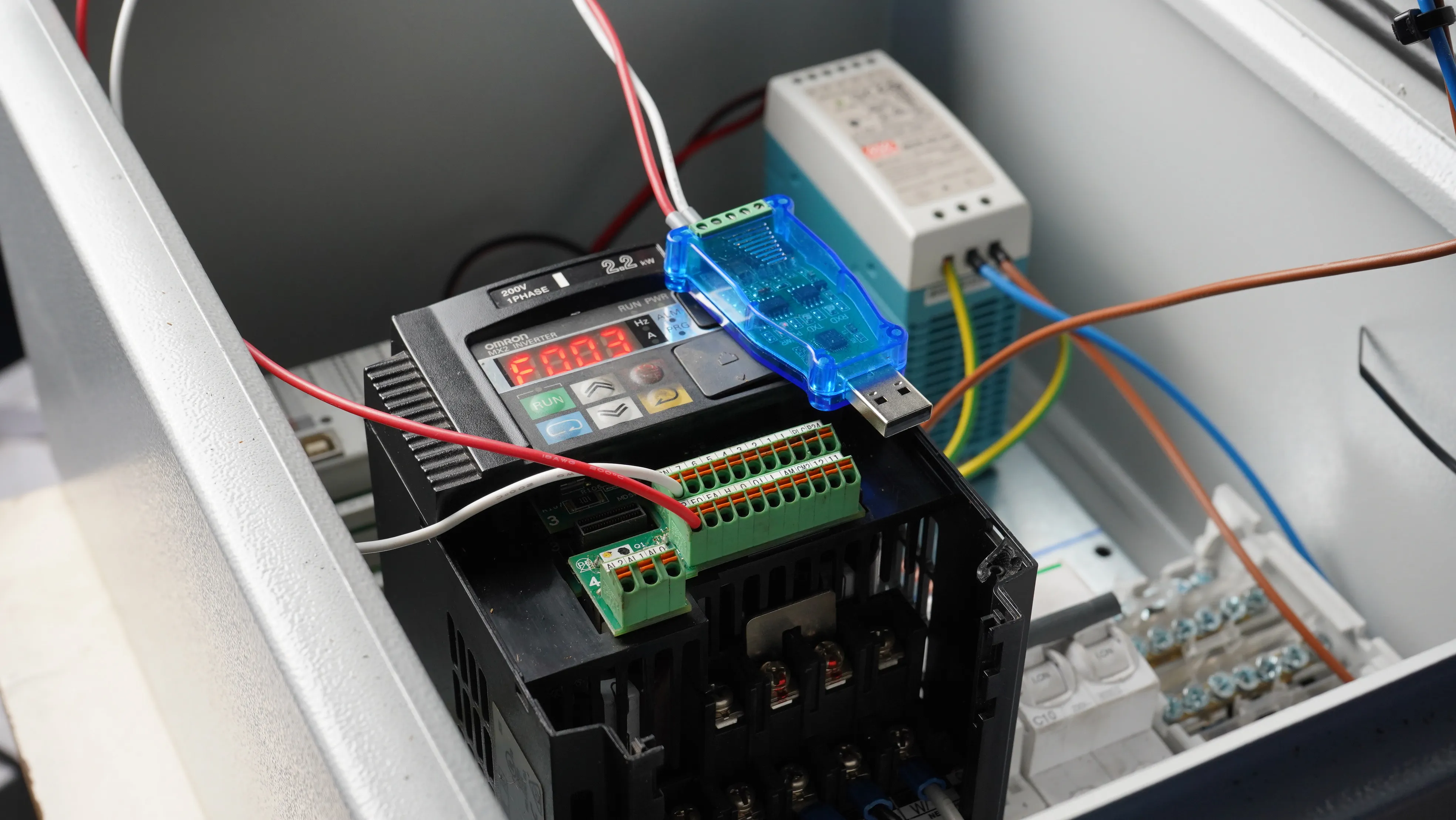
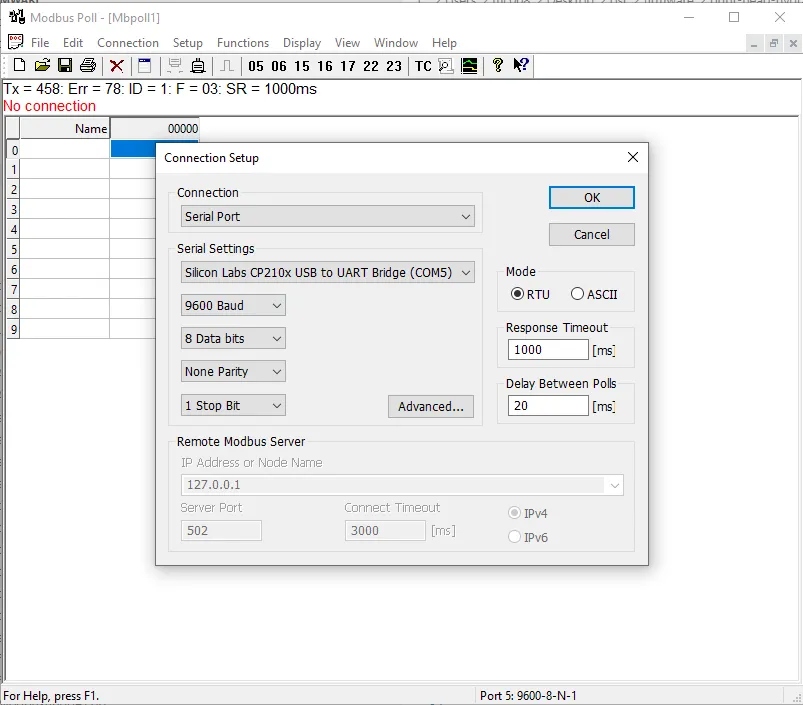
2.3 Test settings, using serial Modbus adapter CP2102 and Modbus poll (see ./tools/MbPoll_v9.4.0_cracked.exe)
2.3.1 Wire the CP2102 USB adapter
2.3.2 Connect
2.3.3 Function - Write Coil
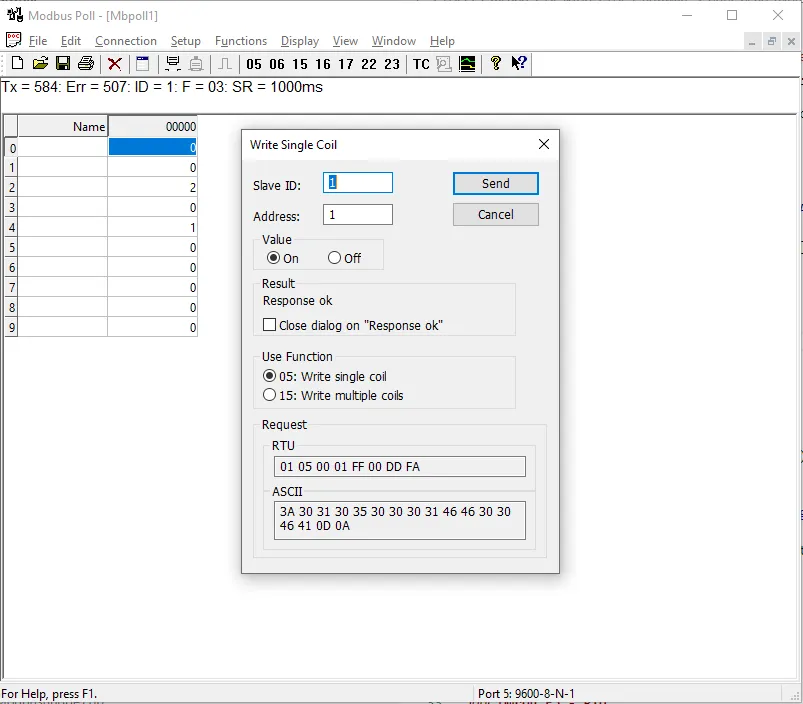
The ‘Run’ LED shoud now be on.
Omron E5 - PID
Section titled “Omron E5 - PID”TCP interface
Section titled “TCP interface”To set the target temperature to 100 Degc on PID1, the complete message for Modbus TCP would be
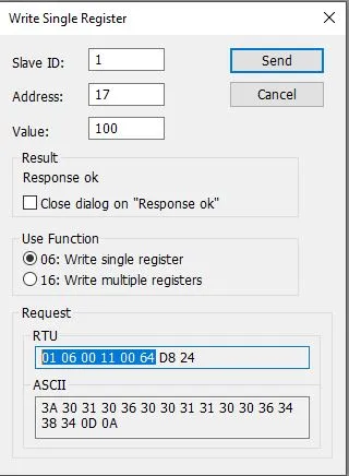
01 06 00 11 00 64 D8 24
01: slave id06: Modbus verb / function code, in this case WRITE HOLDING REGISTER11: address (17)00 64: value (100), 2 bytesD8 24: CRC, 2 bytes. Since it’s TCP, this isn’t evaluated and can be ignored on the Controllino - PlasticHub firmware (see ’./firmware/Mudbus.cpp’](./firmware/Mudbus.cpp)).
In order to fake a Modbus message, all we need is 01 06 00 11 00 64 but we also have to prefix it with the TCP overhead (d2 8d 00 00 00 06)
|---- TCP Overhead----- | -------- Modbus ---- |
d2 8d 00 00 00 06 | 01 06 00 11 00 64
In example, we can send this via Hercules :
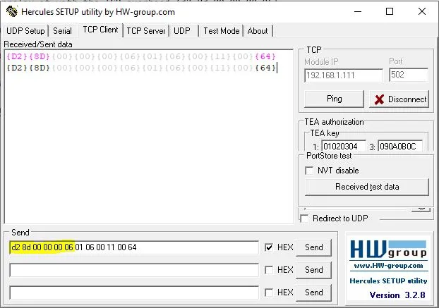
The TCP overhead (d2 8d 00 00 00 06) is created as follow:
d2 8d: Transaction identifier, 2 bytes00 00: Protocol identifier, 2 bytes00 06: Length of the message, 2 bytes
Clearpath - Teknic Servo
Section titled “Clearpath - Teknic Servo”-> White (Input A+) -> DIR -> (MB_STEPPER_DIR_0 -> CONTROLLINO_D18)-> Black (Input B+) -> PULSE -> (MB_STEPPER_PULSE_0 -> CONTROLLINO_D17)-> Blue (Enable +) -> 24V-> YELLOW (Input B-) -> GND-> Brown (Input A-) -> GND-> Orrange (Enable B-) -> GND
### Omron - Optional
- [Brake Resistor](https://www.farnell.com/datasheets/2923188.pdf)